How to Dial In Perfect 3D Print First Layers Every Single Time
Ask any experienced 3D printing enthusiast about the secret to reliable prints, and you’ll get the same answer every time: it all comes down to the 3d print first layer.
The first layer serves as the foundation for your entire model. If the extruded plastic fails to adhere properly to the build plate, your print will warp, detach halfway through a 12-hour job, or turn into a mess of spaghetti.
Whether you are running an open-frame FDM printer or a high-speed enclosed setup, mastering bed leveling, Z-offset tuning, and surface preparation will eliminate over 90% of your printing failures. Here is your step-by-step guide to getting a perfect first layer on every single print.
1. Reading the “Squish”: Diagnostic Visual Guide
Before adjusting physical knobs or digital slicer settings, you must understand what a proper first layer looks like. As the nozzle moves across the build plate, it should gently flatten the extruded filament line against the surface—a metric known in the community as filament squish.
Visual Indicators to Watch For:
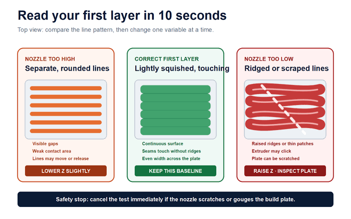
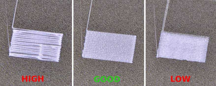
- Nozzle Too High (Under-squished): The extruded lines look like round cylinders laid next to each other. Visible gaps exist between adjacent lines, and the filament easily pulls away from the bed with a finger flick.
- Nozzle Too Low (Over-squished): The nozzle scrapes across the build plate, pushing filament sideways into rough, raised ridges. Extremely thin or translucent patches appear, and the extruder motor may begin clicking due to back pressure.
- Just Right: The extruded filament is flattened into a smooth ribbon. Adjacent lines touch seamlessly with no gaps between them, leaving a flat, uniform surface texture without jagged ridges.
2. Tramming vs. Auto Bed Leveling (ABL)
A common misconception among beginner makers is that an Auto Bed Leveling (ABL) sensor—such as a CR Touch or BLTouch—magically levels a physically crooked print bed.
In reality, ABL sensors create a digital mesh to compensate for minor bed warping. However, your print bed must still be trammed (parallel to the gantry) for the sensor to work effectively.
1.Thermal Pre-Heat:Always level at operating temperatures to account for heat expansion.
Preheat your print bed to 60°C (for PLA) or 70°C+ (for PETG/ABS) and your nozzle to 150°C. Metals expand when heated, so leveling a cold bed will result in an inaccurate nozzle distance during live printing.
2.Manual Tramming (The Paper Test):Establish physical parallelism across all four corners.
Home your printer’s axes. Move the print head to each of the four bed adjustment leveling screws. Slide a standard sheet of copy paper (roughly 0.1mm thick) between the nozzle and bed. Adjust the leveling knobs until you feel light, smooth friction on the paper. Repeat this process twice, as adjusting one corner alters the height of the opposite corner.
3.Run Auto-Bed Mesh Calibration:Let your probe map minor bed surface imperfections.
If your machine features a leveling sensor or load cells, initiate a mesh leveling sequence from the printer control screen or web interface (such as Klipper or OctoPrint). Save the mesh matrix to your printer’s EEPROM.
3. Fine-Tuning Your Z-Offset
Even if your bed is perfectly flat, your Z-offset determines the exact digital distance between the nozzle tip and the homed probe trigger point.
While the paper test gets you into the right ballpark, live-tuning during a test print is essential for perfection.
- Download a First Layer Test File: Print a 1-layer square (e.g., a 100mm x 100mm x 0.2mm patch) or a 5-point corner calibration test from communities like Printables or Thingiverse.
- Observe the Perimeter Outline: As the printer lays down the skirt or brim, watch how the plastic lands.
- Adjust Z-Offset on the Fly: Access your printer’s screen or web interface (e.g., Mainsail/Fluidd) and locate the Z-Offset setting.
- Move in tiny increments (0.01mm to 0.025mm at a time).
- Lower the nozzle (negative offset) if lines are separated.
- Raise the nozzle (positive offset) if plastic is digging up ridges.
4. Build Plate Preparation & Cleaning Rules
Even with flawless geometry, dust, finger oils, and plastic residue will ruin bed adhesion. Follow these maintenance habits to keep your build surface sticking cleanly:
| Build Plate Type | Recommended Cleaning Solution | Adhesion Aid Needed? |
| Textured PEI Sheet | Warm water + dish soap (Dawn), 90%+ IPA between prints | Rarely needed for PLA/PETG |
| Smooth PEI Sheet | 90%+ Isopropyl Alcohol (IPA) | Use glue stick as release agent for PETG |
| Glass Bed | Glass cleaner or 90%+ IPA | Glue stick or hairspray helps adhesion |
| Purna/Satin Sheets | 90%+ Isopropyl Alcohol | None required for standard filaments |
Pro Tip: If your prints suddenly stop sticking to a PEI sheet despite cleaning with Isopropyl Alcohol, take the sheet to the sink and wash it thoroughly with warm water and basic dish soap (like Dawn). IPA dissolves oils and spreads them around over time, whereas dish soap breaks down and washes grease away entirely.
5. Slicer Tweaks for Unstoppable First Layers
If hardware calibration is dialed in but tricky filaments like PETG or ABS still warp, make these adjustments in your slicer (such as PrusaSlicer, OrcaSlicer, or Cura):
- Initial Layer Height: Set your first layer height to 0.2mm or 0.24mm, even if printing thinner subsequent layers (e.g., 0.12mm). A thicker first layer provides a forgiving tolerance for bed variance.
- First Layer Line Width: Increase first layer line width to 110%–125% (e.g., 0.5mm width on a 0.4mm nozzle). This pushes additional material down, maximizing surface contact area.
- Disable Cooling Fans: Keep your cooling fan turned completely off (0%) for layers 1 and 2. Rapid cooling causes thermal contraction, pulling filament corners up off the bed.
- Slow Down Printing Speed: Cap first layer speeds to 15–25 mm/s. Giving the melted plastic extra time to transfer heat to the bed drastically improves mechanical bonding.